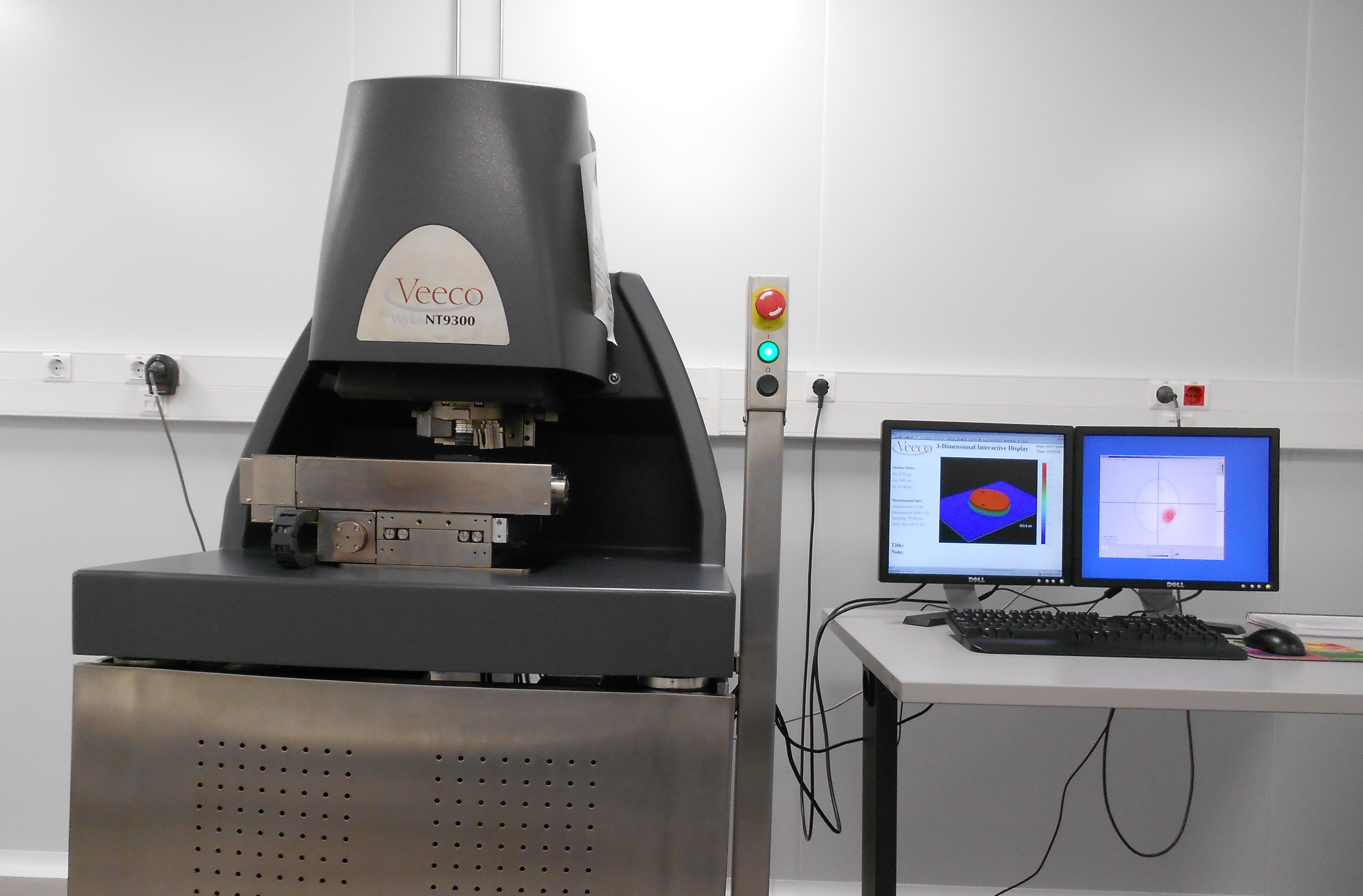
Optical interferometry
Description
An optical profiler passes white light through a beam splitter, where the beam is divided in two. One part is directed to the sample (test beam) and the other part is directed to a super smooth reference mirror (reference beam). When the surface of the sample is focused, the light reflected from the two surfaces (test and reference beams) recombines and a pattern of interference is obtained. This interference pattern can be used to calculate the height of each point on the sample surface with very high resolution.
Our Wyko NT9300 interferometric microscope supports two measurements modes:
- PSI mode (Phase Shifting Interferometry): the path length of the beam reflected on the sample surface is altered by a mechanical translation system. Each optical path causes a lateral shift in the interference fringes. The equipment camera records a sequence of this interference patterns which are combined by computerized calculations to determine the surface 3D profile. PSI mode requires using a narrow band light source, in NT9300 a 535-nm filter is used (green light). PSI is a high resolution mode which can measure steps of less than 1 nm with a very low noise level, however it cannot obtain a correct profile for object with steps higher than 135 nm (1/4 of green light) or roughness higher than 30nm.
-
VSI mode (Vertical Scanning Mode): the microscope is translated vertically during the measurement as the camera periodically records frames. At each high, different part of the surface is focused and at maximum modulation. By recording the height of the translator at maximum modulation the system can determine the height of each point (pixel). VSI can reach height resolutions up to 3 nm with a maximum vertical scan length of 10 mm. The maximum scan speed of NT9300 operating in VSI mode is 25 µm/s.
Key features
- Sample requirements: reflective surface.
- Z-axis motorized Improved Modular Optics Assembly (IMOA).
- The IMOA contains a CCD camera and a Multiple Magnification Detector (MMD) with 3 Field of View (FOV) lenses (0.55X, 1X, 2X) which are motorized.
- Motorized X-Y sample stage, which allows automated stitching measurements.
- Two different magnification objectives (10X, 50X) mounted on a motorized turret and tip/tilt cradle (maximum ±4°).
- Integrated vibration-isolated table.
- Maximum z-resolution of 3nm (VSI mode) and under 1nm (PSI mode).
- Vision software (version 4.20 update2) for measurements and processing data (surface parameters such as roughness or step calculation, contour plot, 2D/3D plots, databases).
Contact
In order to book the equipment and for more information, please contact Judit Buxadera (tecnics.multiescala@upc.edu).
Share: